This is the first article of a three part series on how Synergy uses laser scan data to generate smart as-built 3D models. The example model used in this article is from Eaton’s training facility in Houston and is supplied courtesy of LFM Software and AVEVA. Disclosure: Synergy was an official beta tester for AVEVA Laser Modeler during its development phase in 2011.
Laser scanning is the de facto standard technique for accurately generating or as-building the 3D model of an existing facility. The AVEVA Laser Modeler software application allows for high definition laser scan survey data to be imported directly into a 3D design environment (e.g. PDMS).
The laser scan survey data consists of multiple point clouds based on the different laser scans taken at various locations around the project site. The Laser Modeler application is able to consolidate all of the survey data into a single combined point cloud, which can then be imported into a 3D design environment. This allows for:
- Virtual walk / zoom / rotate operations
- Accurate measurement of all laser scan data
- Conversion of laser scan point cloud data into a smart 3d intelligent design model
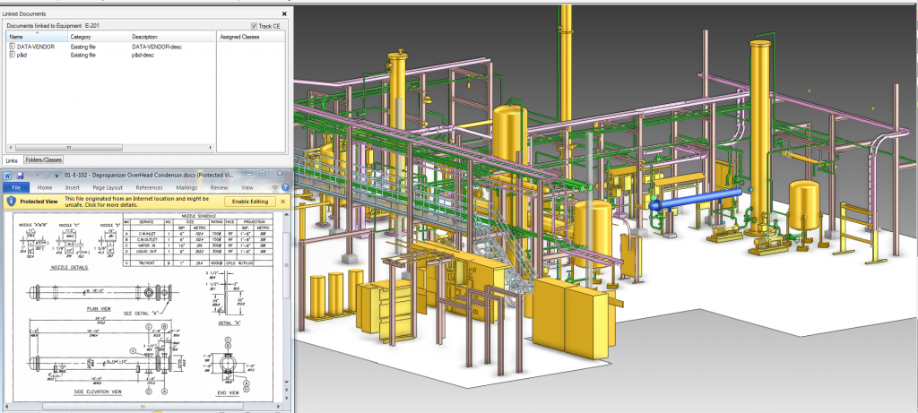
- Addition of Hyperlinks to referenced external documents such as process P&IDs, mechanical data sheets, etc.
- Clash check review of brownfield modifications against laser scan data

BubbleView Environment
The BubbleView environment is used to interrogate the laser scan point cloud data in high definition, allowing the designer to place themselves at any laser scan camera location and look around (similar to Google Street View). Comprehensive smart 3D modeling / measurement and clash check facilities are also available and can be used seamlessly within the high-definition BubbleView environment.
Standard Smart 3D Model Conversion Process
The standard approach for converting a laser scan survey into a smart 3D model is a twofold process.
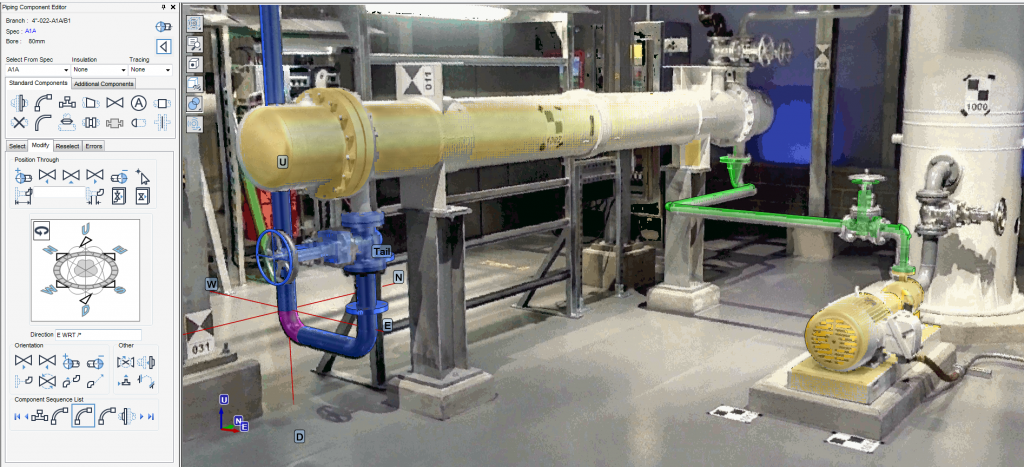
1. Back-modelling: is the process of turning a laser scan point cloud into 3D model objects. The designer selects a specific group of laser scan points from within the BubbleView environment that belongs to the surface of a pipe, structure or piece of equipment and then selects an appropriate 3D model component from the catalogue. Note that catalogue components are all specification-based and imbued with metadata such as pipe specification, part number, industry standard that the component complies to, etc.
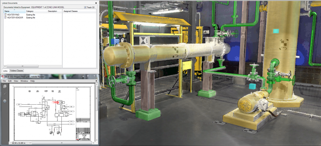
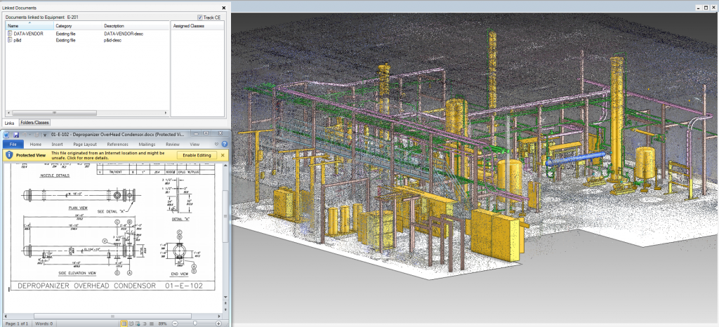
2. Hotspot Hyperlinking: is the process of linking external data to objects in the 3D model. Practically any form of external data can be linked, including project documents (e.g. P&IDs, equipment data sheets, etc), site survey data (e.g. photos, test reports, etc) and maintenance data (e.g. procedures, records, etc).
The resulting 3D model can be checked by overlaying the point cloud on top of the 3D model and ensuring that all objects have been adequately modelled.
The final product is a fully intelligent 3D design model:
See also