There is often a disconnect between engineering houses and fabricators, particularly small to medium scale fabricators who may have little or no in-house 3D cad system capabilities. Typically what normally happens at the end of the project design phase is that the engineering company hands over their 3D model to the fabricator and offers little to no support regarding pipe spooling activities.
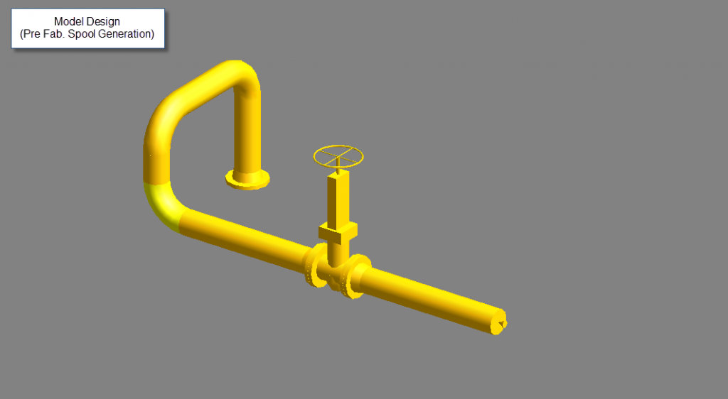
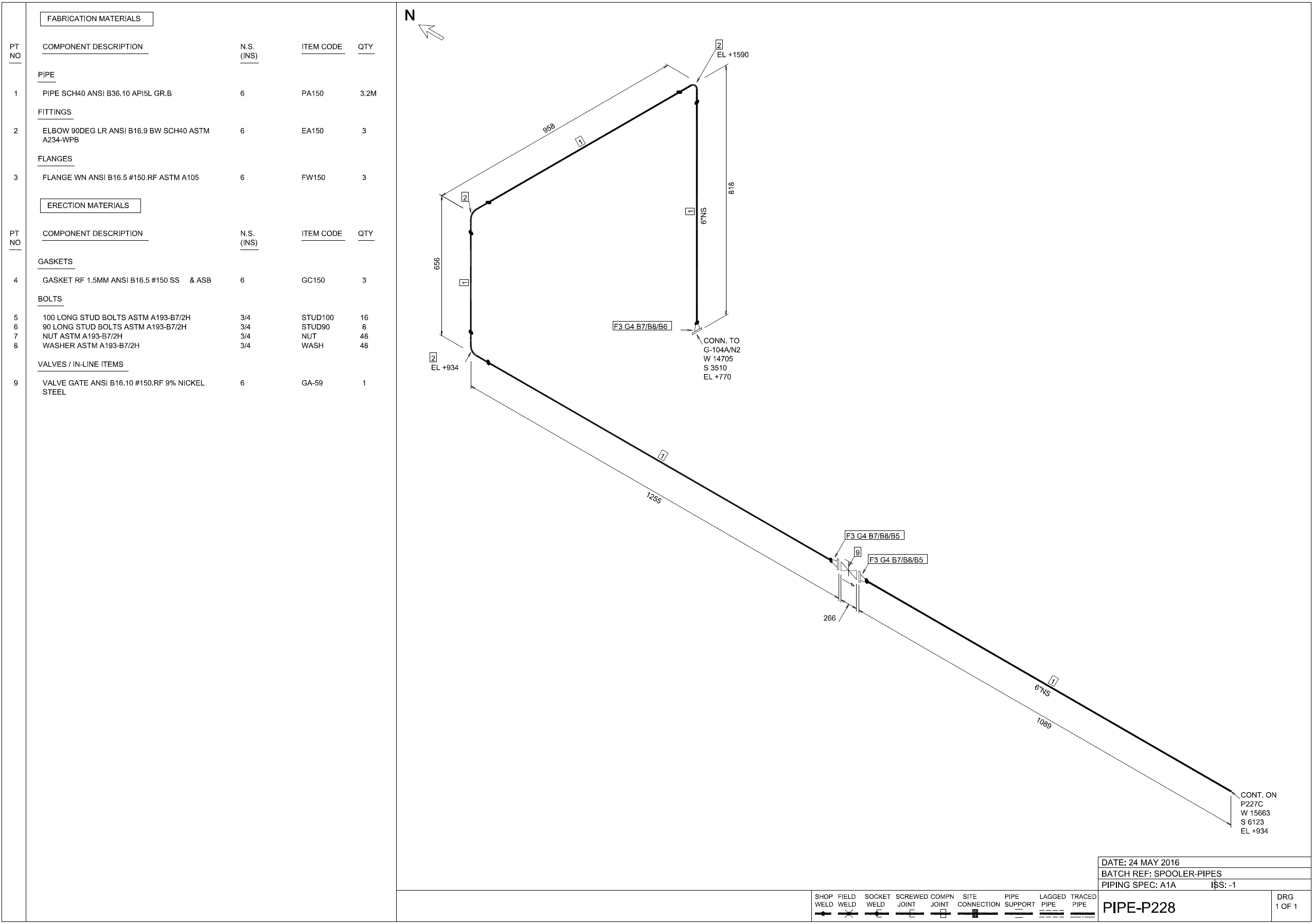
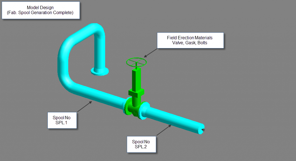
The 3D Project Design Model is typically fit to produce project isometric drawings detailing pipe lines in their entirety, but what the fabricator actually needs is fabrication pipe spooling drawings, i.e pipe lines split up into manageable pipe spool sections, complete with numbered welds and pipe spool sections. It is the spooling drawings that are given to the shop floor for fabrication, not the project isometrics.

Rather than producing pipe spool drawings directly from the 3D model, most small to medium sized fabricators only use the 3D model to export pipe isometrics into a 2D drawing package (e.g. AutoCAD). And then go on to manually annotate the required weld / spool numbering etc. This is both time consuming and prone to human error. For example, in one recent project, the fabricator accidentally orientated the north arrow incorrectly on their AutoCAD pipe spool drawing, resulting in the fabrication of mirror image spools that didn’t fit on site.
Generating spooling drawings directly from the 3D model
In theory, 3D design software packages such as PDMS and Smartplant 3D actually have pipe spool drawing production as part of their core workflow, with supporting tools built-in to assist in spool generation. However in practice, these tools are not always used as it requires a fabricator who either has in-house engineering capabilities or external support from an engineering house. In the ideal workflow, once the 3D model is handed over to the fabricator, the design cannot be changed (e.g. pipe locations and pipe routes). Only pipe splitting and weld type and locations can be added.
The process for generating the spooling drawings more efficiently from the 3D model is as follows:
- Upon receipt of the 3D model, verify the model prior to acceptance by performing clash checks, data consistency checks, etc.
- Examine the model and plan construction sequences.
- Prior to pipe spooling, perform another clash check for the lines to be spooled
- Produce pipe spool drawings for clash-free lines, with input from fabricator regarding pipe spool splitting, weld type and locations. Annotations such as weld and pipe spool numbers are generated automatically.This ensures all pipe spool drawing are in alignment with 3d design model as the pipe spool drawing process is complete automated.
- Produce reports of interest from the model database by pipe spool , e.g. material, weld reports, weight cofg reports, etc